Part 3 - Logic Gates
For a complete table of contents of all the lessons please click below as it will give you a brief of each lesson in addition to the topics it will cover. https://github.com/mytechnotalent/Reverse-Engineering-Tutorial
In our last tutorial we spoke briefly about binary to which we represent as either true or false. In binary, true is equal to 1 and false is equal to 0. Computers are ultimately built on this very simple concept to which at the core we have four possible logic gates which can be combined in an infinite amount of sequences.
Let’s start with the AND Gate below.
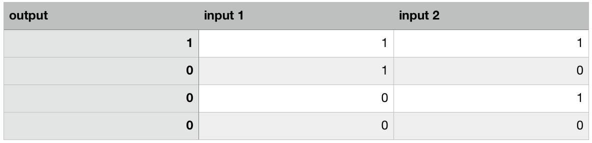
In an AND Gate there are two binary values to which outputs 1 only if both binary values are 1.
The NOT Gate is represented below.
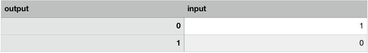
In a NOT Gate it simply takes a single binary value and negates it.
The OR Gate is represented below.
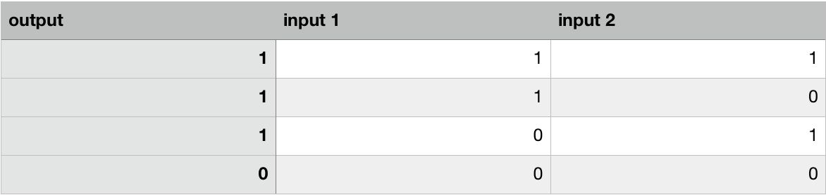
In an OR Gate only one of the inputs has to be 1 in order to output a 1.
The XOR Gate is represented below.
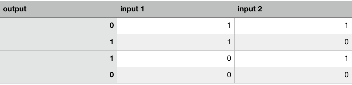
In an XOR Gate if both inputs are either 0 or 1 the output is 0.
"The Why..." Ok so why am I going over this? What does this have to do with understanding Assembly or Reverse Engineering? Well... At the very CORE of all processors are these simple logic gates that when combined together form complex instructions. I could spend literally years showing you this in practice however I will leave that for another to pick up the charge. What is important is that you get a basic understanding of what is going on here when we ultimately see instructions such as AND, OR, XOR, etc when we code in Assembly and more importantly when we Reverse Engineer.
Stay tuned! We will be building our own very SIMPLE Operating System shortly!