Part 20 - Instruction Code Handling
For a complete table of contents of all the lessons please click below as it will give you a brief of each lesson in addition to the topics it will cover. https://github.com/mytechnotalent/Reverse-Engineering-Tutorial
A CPU reads instruction codes that are stored in memory as each code set can contain one of more bytes of information that guide the processor to perform a very specific task. As each instruction code is read in from memory, any data needed for the instruction code is also stored and read into memory.
Keep in mind, memory that contain instruction codes are no different than the bytes that contain the data used by the CPU and special pointers are used to help the CPU keep track of where in memory data is and where instruction codes are stored.
A data pointer helps the CPU keep track of where the data area in memory starts which is the stack. When new data elements are placed in the stack, the stack pointer moves down in memory and as data is read from the stack the stack pointer moves up in memory. Please review Part 15 – Stack if you don’t understand this concept.
The instruction pointer is used to help the CPU keep track of which instruction codes have already been processed and what code is to be processed next. Please review Part 12 – Instruction Pointer Register if you don’t understand this concept.
Each and every instruction code must include an opcode that defines the basic function or task to be performed by the CPU to which opcodes are between 1 and 3 bytes in length and uniquely defines the function that is performed.
Lets examine a simple C program called test.c to get started.
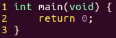
All we are doing is creating a main function of type integer to which it has a void parameter and returning 0. All this program does is simply exit the OS.
Lets compile and run this program.

Lets use the objdump tool to and find the main function within it.

Here is a snippet of the results you would get by running the above command. Here are the contents of the main function. Keep in mind the below is in Intel syntax as we spoke about in the last tutorial.
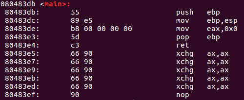
On the far left we have the corresponding memory addresses. In the center we have the opcodes and finally on the right we have the corresponding assembly language in Intel syntax.
To keep this simple, lets examine memory address 80483de where we see op codes b8 00 00 00 00. We can see that the b8 opcode corresponds with the mov eax, 0x0 instruction on the right. The next series of 00 00 00 00 represents 4 bytes of the value 0. We see mov eax, 0x0 therefore the value of 0 is moved into eax therefore representing the above code. Keep in mind, the IA-32 platform uses what we call little-endian notation which means the lower-value bytes appear first in order when reading right to left.
I want to make sure you have this straight in your head so lets pretend the value above was:
mov eax, 0x1
In this scenario the corresponding opcode would be:
b8 01 00 00 00
If you are confused it is ok. Remember little-endian? Keep in mind eax is 32-bits wide therefore that is 4 bytes (8 bits = 1 byte). The values are listed in reverse order therefore we see the above representation.
I look forward to seeing you all next week when we dive into the details about how to compile a program.